Feature Rich Tools to Process Field Survey Data
 Stringer Topo provides you with the tools you need to convert raw observation files into a dedicated graphical survey editor, through to automated import of coordinate points.
Stringer Connect supports a wide variety of data recorders and all the common data file formats surveyors including: Leica GSI, Trimble, Topcon and Sokkia outputs.
By setting a project, multiple survey files can be imported. Stringer Topo maintains the original file and provides users with editing and adjustment capabilities for all survey observations.
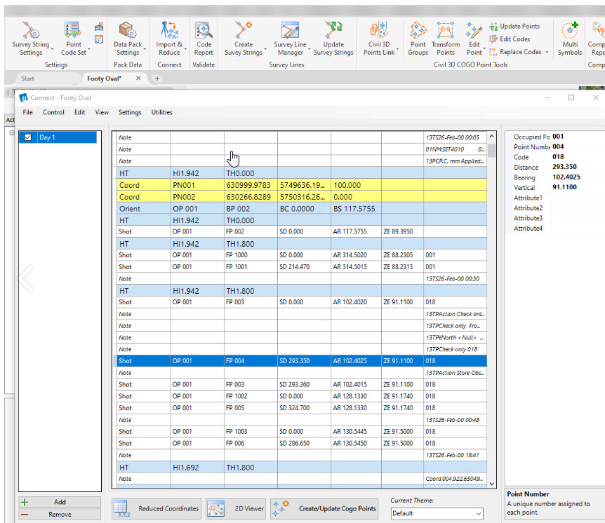
An audit check is performed as you make changes, so you can immediately identify added, edited and ignored entries.
Within Stringer Connect you can click on any entry to enable editing and zoom to the location in the drawing if points have been created. Any edits you make can be restored back to the original, and any entry can be set to ignore so it doesn’t contribute to the coordinated point output.
You can add in a forgotten target height adjustment in just a few button clicks and a matter of seconds.
Because Stringer Connect maintains a link to the points created in the drawing, you can see the effect of changes you make in the survey observations immediately. A dedicated 2D Viewer to see all side shots, control points and observations, updating as you edit the survey entries.
You can underlay an aerial photo, highlight back sight errors, step through the survey pickup progress and turn control point pickups on and off.
Click on a line or point to jump to it in the survey entry list.
Stringer Connect allows you to easily adjust your control points by typing the corrected coordinated direct in the cells, importing a file of points to update the co-ordinates or getting the coordinates adjusted by reading COGO Point coordinates from a drawing.
Control points can be directly managed in Stringer Connect via a dedicated Control Points form. You can import a control points file, export the control points to the drawing and edit control points from the drawing.
Transfer COGO Points directly to the drawing at the click of a button, displayed according to your point descriptions by layer, marker and label. The addition of survey strings, linework and surface output can be completely automated
Extensive COGO Point Functionality
If you are working inside Civil 3D, Stringer Topo works directly with and expands on Civil 3D COGO points.
For AutoCAD and BricsCAD users, Stringer Topo is enhanced with full COGO point tools in the drawing.
In all platforms, Stringer Topo provides support for COGO points, with customizable point presentation based on the point code, comprehensive point editing tools, point labelling control and the ability to group points for output and surface generation.
In AutoCAD and BricsCAD, point display is managed by a block with attributed text, so you are in complete control of the look and feel of each point. For Civil 3D users, we leverage the Civil 3D COGO points for managing the display output.
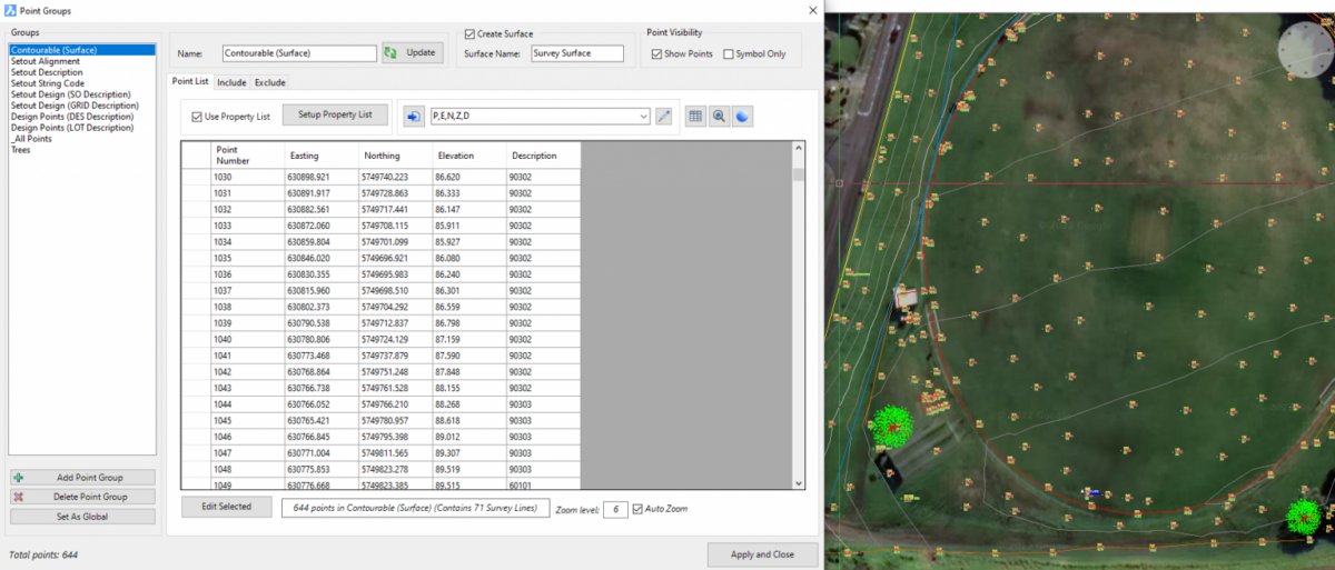
Point Groups provide categorizing of points, allow bulk edit control over display and establish the points used in constructing a surface. The Point Group toolset allows for adjustment of point datum elevations, incrementing of point numbers, editing of display styles, dynamic positioning to other objects and more.
Output options include a click export to export points to file, add tables to the drawing and transfer the points (and survey strings) to Google Earth.
COGO Points support a number of inbuilt Point Properties (such as point number, elevation, style) and allow for the user to create any Point Property field required. This provides opportunity to include additional attribute information with each COGO point, including text display on the point and inclusion in point tables and file output.
COGO Point Tools for Civil 3D Users
If you are using Civil 3D, Stringer Topo can expand on your current functionality by extending additional Point Properties to Civil 3D COGO Points via User Defined Property tables, so if you want to include alignment information or other attributes in your Civil 3D point output you can.
As well, the dynamic link between Stringer Topo and Civil 3D points expands point editing capabilities:
- Control Civil 3D point positions by dynamically referencing another object (such as an alignment or surface)
- Extending Helmert and Affine transformations to Civil 3D points
- Enabling storage of extended properties onto Civil 3D Points
- Control Civil 3D point positions by dynamically referencing another object (such as an alignment or surface)
- Extending Helmert and Affine transformations to Civil 3D points
- Enabling storage of extended properties onto Civil 3D Points
If you are working inside AutoCAD or BricsCAD, then you benefit from all of the above functionality as well as the ability to easily switch on/off the display of particular property text and a dedicated multi point code editor.
You can also grip edit move points in the drawing, as well as use CAD tools to delete.
We have an extensive toolset for creating points:
- Import point files, including transformation between coordinate systems
- Create points that adopt the surface elevation
- Create points by dynamic reference to other objects
- Create points using polyline geometry
- Create points on a grid of coordinates
- Convert text, CAD points and blocks into COGO Points, including multiple options to inherit elevation information from the objects in the drawing
Automated Survey Linework and Breaklines
Stringer Topo makes it quick and easy to add, edit and remove breaklines and survey linework (Survey Strings) directly inside the drawing. With a wide collection of point and string editing tools you can quickly correct any pickup errors and get to the finished product.
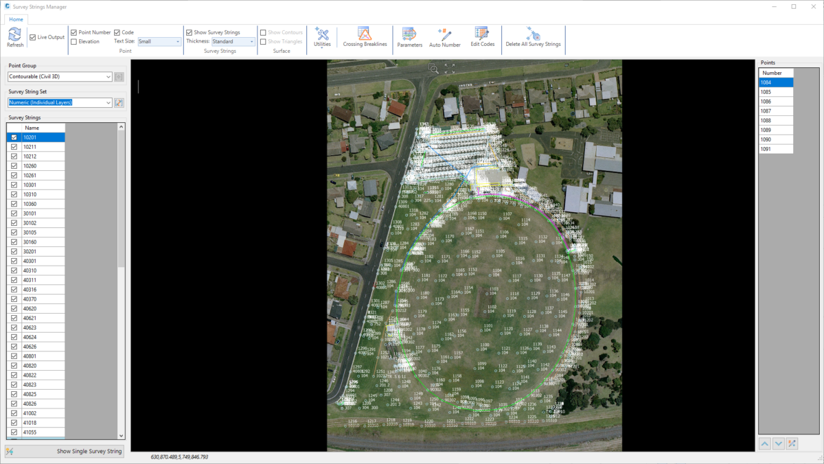
Stringer Topo allows users to separately control, on a point Code basis, whether to add surface breaklines, 2D polylines or 3D polylines when points are created or edited. You get to pick the layers for your 2D and 3D polyline output to the drawing, and can even add section templates to apply multiple offset survey strings from your point pickup.
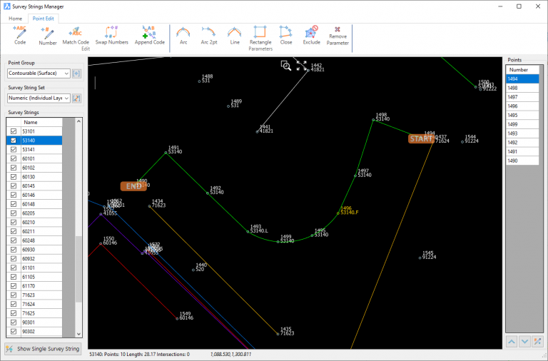
Survey Strings can be quickly edited in a dedicated editor window, with all edits updating immediately in the drawing. Edits can be applied to points to improve survey string outputs, either in the field or in the office. Using the Survey Line Manager window you can easily:
- Navigate to any string by list or graphical selection
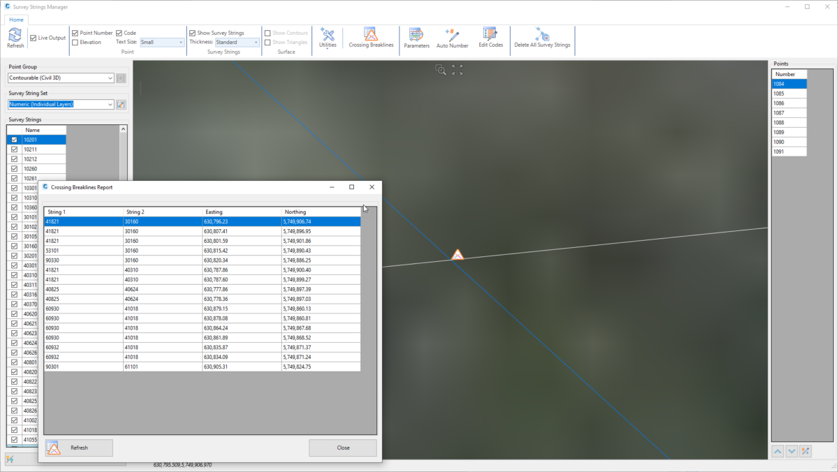
- See a highlight for self-intersecting strings and see an interactive report of crossing breaklines
- Change the order of points connecting survey strings, without needing to change point numbers in the drawing
- Click on any String or Point enables a dedicated ribbon of commands:
- For Strings
- Reorder strings to fix out-of-sequence pickup using AI, distance to next or other method
- Delete line segments based on selection or length
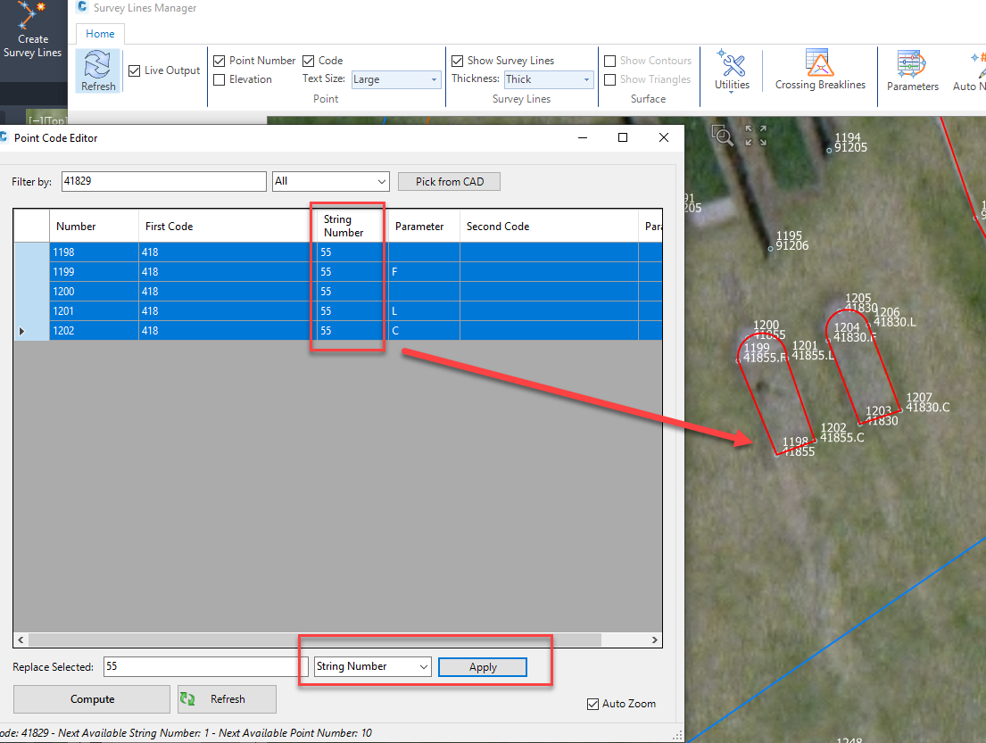
- Join strings and embed new strings between points, by applying multiple codes to the points
- For Points
- Edit point code or point number
- Match codes by point selection and swap point numbers
- Append codes to a point by selection of another point
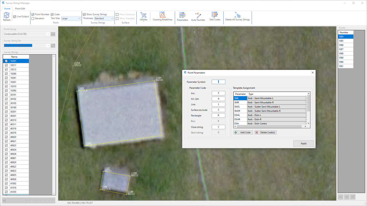
- Apply Code Linework Parameters to enhance survey string production output: create arcs between points, close off three points to form a rectangle, close strings and attach Templates
As well as editing via the Survey Line Manager, we’ve enabled the most common edits as keyboard shortcuts to apply directly in the drawing.
Achieve survey fixups in minutes using Stringer Topo that would otherwise take hours.
3D Model Analysis
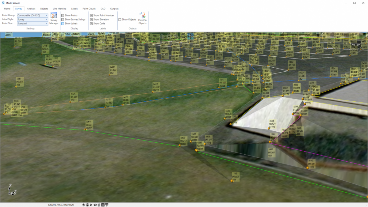
Model Viewer displaying COGO Points and point labels.
While you are editing your COGO points and Stringer Topo is updating the breaklines and surface, you can review the surface results via the 3D Model Viewer. The Model Viewer is a separate window showing you a data accurate, fully rendered model of your surveyed surface/s, with click button exaggeration to highlight any issues and visual styles to show or hide the triangulated mesh.
You can also display your surveyed points and strings, and add 3D objects from your point pickup. This gives you another view into the survey to ensure that both the surface and survey output is correct.
Survey Tools and Legend Tables
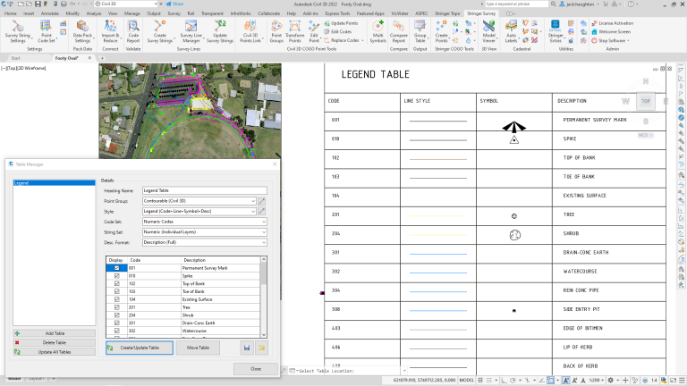
Stringer Topo includes a range of tools to output legend tables, apply multi scaled symbols on a single point, undertake survey quality reporting and assist with cadastral survey drafting.
Cadastral Tools
Legend Table
You can generate a Legend Table, as well as a Point and Survey String table, at the click of a button, displaying points and strings used in the drawing.
The table is highly configuration for you to manage the columns of data, headings and presentation output.
Multi Symbols
Set up your tree symbols (or other multi block symbols) to include independent scaling of the trunk and canopy, as well as assignment of a 3D tree block which can be viewed in Model Viewer. The Multi Symbols command allows as many scaled blocks as required to be inserted on a single point pickup.
Conformance Reporting
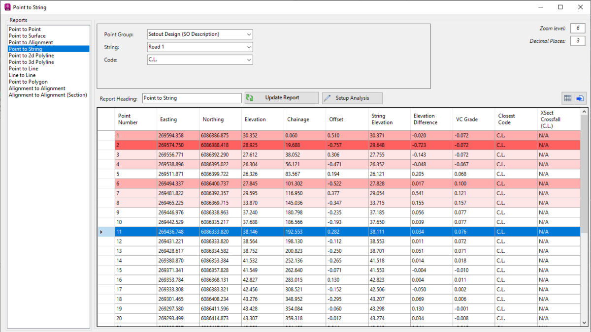
Auditing tools are included for you to check and confirm the quality of your survey by comparing, analysing and documenting the differences between surfaces, points, alignments, polylines and lines. You can analyse the results to highlight non-compliance to display in the report.
Comparison report results can be output to multiple formats:
- As text in the drawing, colored to match the analysis colors applied
- To Excel, either as a new Excel file or to selected fields in an existing Excel file
- To a comma separated file
- To the drawing as a Table object
A number of cadastral tools are also included – undertake traverse adjustments from polylines and points, label linework, compare linework and label distance/bearing differences, create linework using links, and create radiation tables.
Discover how Stringer Topo can maximize your efficiency
and produce better results in less time.