
The Survey String Settings command is key to controlling how your Point Codes are used in the creation of breaklines, addition of offsets and the creation of 2D and 3D linework.
Form Overview
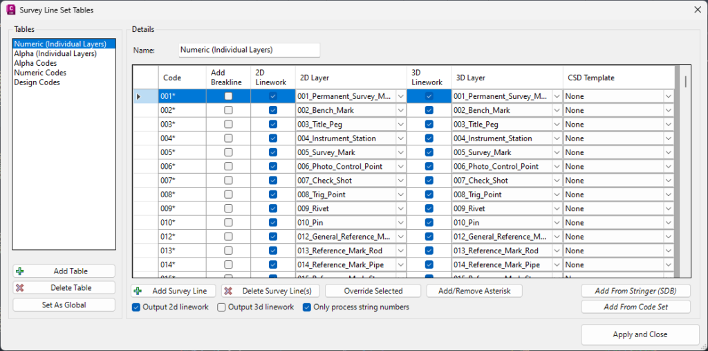
On the left are Tables. You create and name these. They allow you to create collections of Codes (the point descriptions you pick up in the field) that Stringer can automatically use to:
- Add as surface breaklines
- Draw as 2D linework
- Draw as 3D linework
- Include a ‘Template’ – this can create multiple offset polylines from the Code pickup, great for things like kerb.
Use the Add Survey Line button to add new Codes into this list.
When you add a Code, it’s recommended you make use of the Wildcard (Asterisk, *) because that allows a match for what you add before or after the code (wherever you put the wildcard). We added a button at the bottom of the form, Add/Remove Asterisk, to automatically append the * (or remove it) from highlighted entries in the list.
My Tables are Awesome – How do I Make them the Default for Future Surveys?
When you use the Survey String Tables form in a particular survey, all your edits are fully contained in that survey – they don’t automatically become the settings for the next survey. This has benefits, if you are doing something unique in a particular survey.
Most customers set up the tables with the intention they become the ‘template’ for future projects (what we call the Global settings).
Once you’ve set everything up how you like, be sure to click the Set as Global button bottom left and set this as the start point for your next survey. For all the wonks out there (and CAD managers), this updates the file SurveyStringSets.dat which is located in the Stringer Settings folder. How do you get to the Stringer Settings Folder? There is a ribbon command for this in the AutoCAD and BricsCAD versions (we’ll need to add it to the Civil 3D version), but you’ll find it in the folder C:\ProgramData\CSS\ARD\Common\common-10\ . That is, unless you’ve moved the settings folder – if you’ve done that then you’ll already know where this folder lives.
Multi Edit Tools
Now, let’s talk about ‘Overrides’.
You can make mass edits to multiple Codes in your list using the Override Selected button. It’s a four step process:
- Highlight the rows you want to edit – the cells will turn blue
- Click on Override Selected:
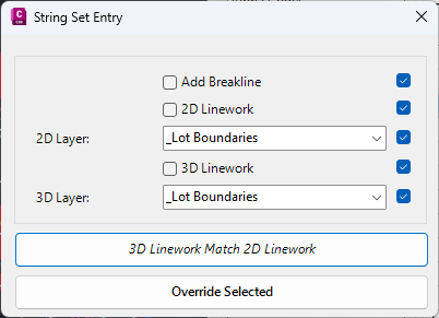
- For all the Codes you highlighted you can control whether those codes create surface breaklines, display 2D linework (including the layer) and display 3D Linework)
BEFORE you click on Override Selected, take note of the tick boxes on the right. You can untick these to NOT override those controls for the code (you don’t usually want to force all Codes to use the same layer for instance)
Note the extra button: 3D Linework Match 2D Linework. We added this from Stringer V24.20. What it does is reads the 2D Layer assigned to each highlighted Code and set that same layer to be the 3D layer. - Click on Override Selected and all those selected Codes will be adjusted.
Importing Codes
From old Stringer to new Stringer
If you have a setup with Stringer Topo (Legacy) in AutoCAD or BricsCAD, the Add from Stringer (SDB) will save you loads of time converting from ‘old school’ Stringer to new. It reads the Stringer Settings file from your old Stringer versions and converts them into the current Stringer Survey String settings.
Note: If you are a Civil 3D user wishing to move from old to new Stringer, you can still use this command to automate the import but you’ll need to modify the Stringer Settings file. Full instructions can be found on this web page: https://stringersurvey.com.au/stringer-topo-v23/. You can also check out this video.
Leveraging the Point Code Set
If you started your setup journey by setting up the Point Code Set, you can cut over the codes from there by using the Add from Code Set button. That will still leave you with the task of setting the breakline, 2D and 3D layer controls but it’s a kickstart into your setup of the string behaviour.
Controlling 2D/3D polyline output
Many surveyors want to issue either a 2D plan or a 3D plan (it’s more rare to issue both in the same drawing).
There are two ‘master’ controls governing whether you output 2D linework or 3D linework for your Codes.
If Output 2d Linework is ticked on, then the software will apply the 2D Linework and 2D layer settings you set up in this table.
If Output 3d Linework is ticked on, then thesoftware will apply the 3D Linework and 3D layer settings you set up in this table.
Well, that’s a quick summary of the Survey Line Settings.